DivideWorks
  • HOME
  • PROJECTS
  • CONTACT

Tracked Vehicle Prototyping Platform

9/27/2015

 
Picture
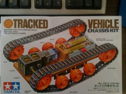
A tracked vehicle makes a great platform for testing sensors, motor drivers, micro-controllers and softwware.  A small chasis, like the Tamiya chasis kit can provide a proving ground for your project before you go full scale.

The chasis kit is an easy way to get started, but  does have some draw backs.  The motor and gearbox you get with the kit has a solid axle, so there is no way to independently control the left and right tracks. To do this you willneed the dual gearbox.  The chasis is also narrow, leaving little room for electronics.  For these reasons I would recommend buying the tread kit and making your own chasis.

Picture
Picture
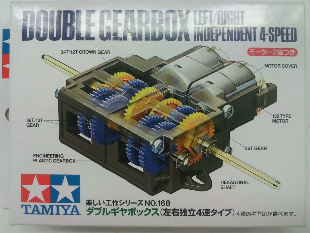
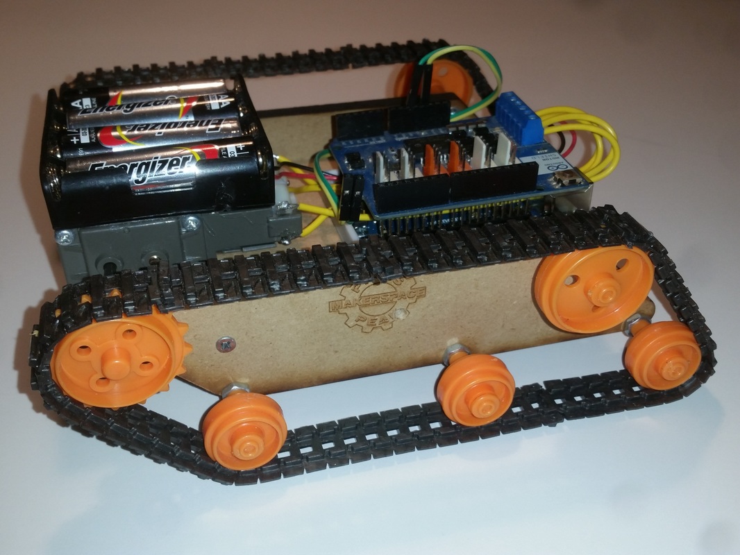
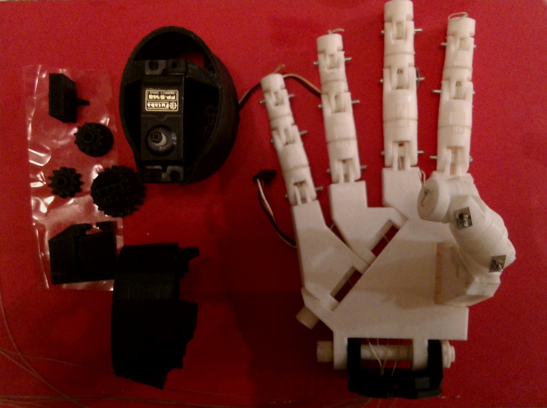
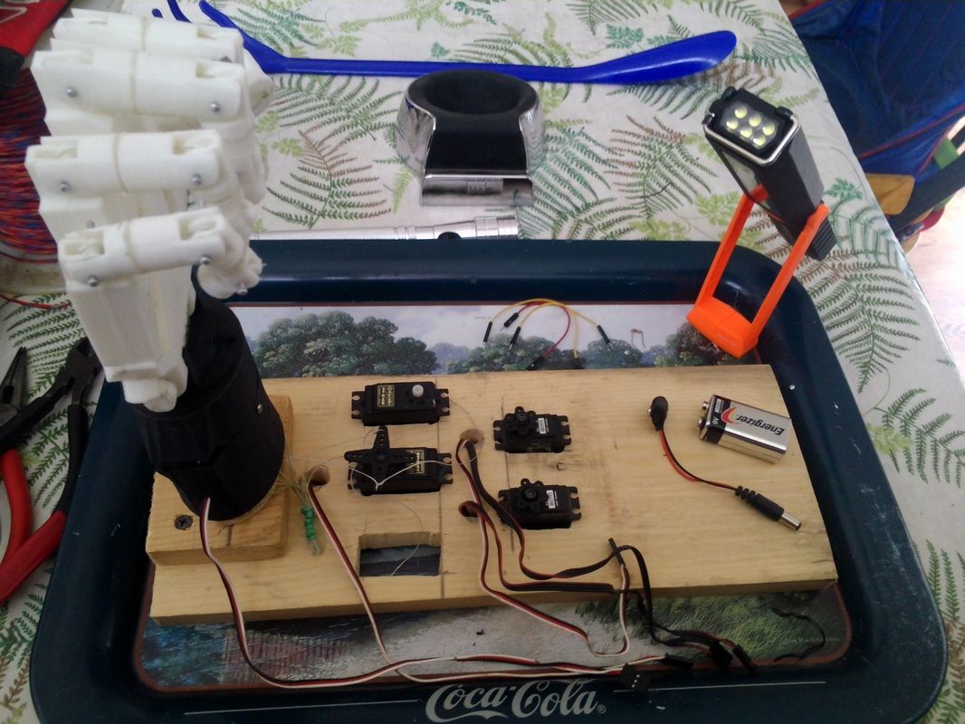
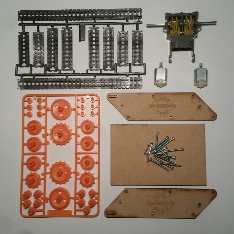
Above you can see one of the Tamiya dual gearbox assemblies.  This one has four possible gear ratios.  In the photo below, you can see I have used a simpler dual gearbox.  This one is slightly smaller, but still gives you two gear ratio options.  I designed a chasis that gave me a tread pattern, ground clearance and platform size advantage over the standard chasis kit.  I found 3mm bolts worked fine for the axles, allowing improved groung clearance over the standard through axles.
Picture
Picture
Picture
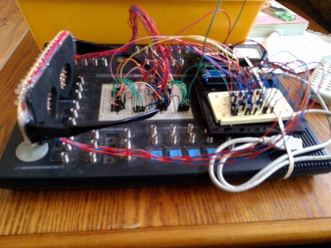
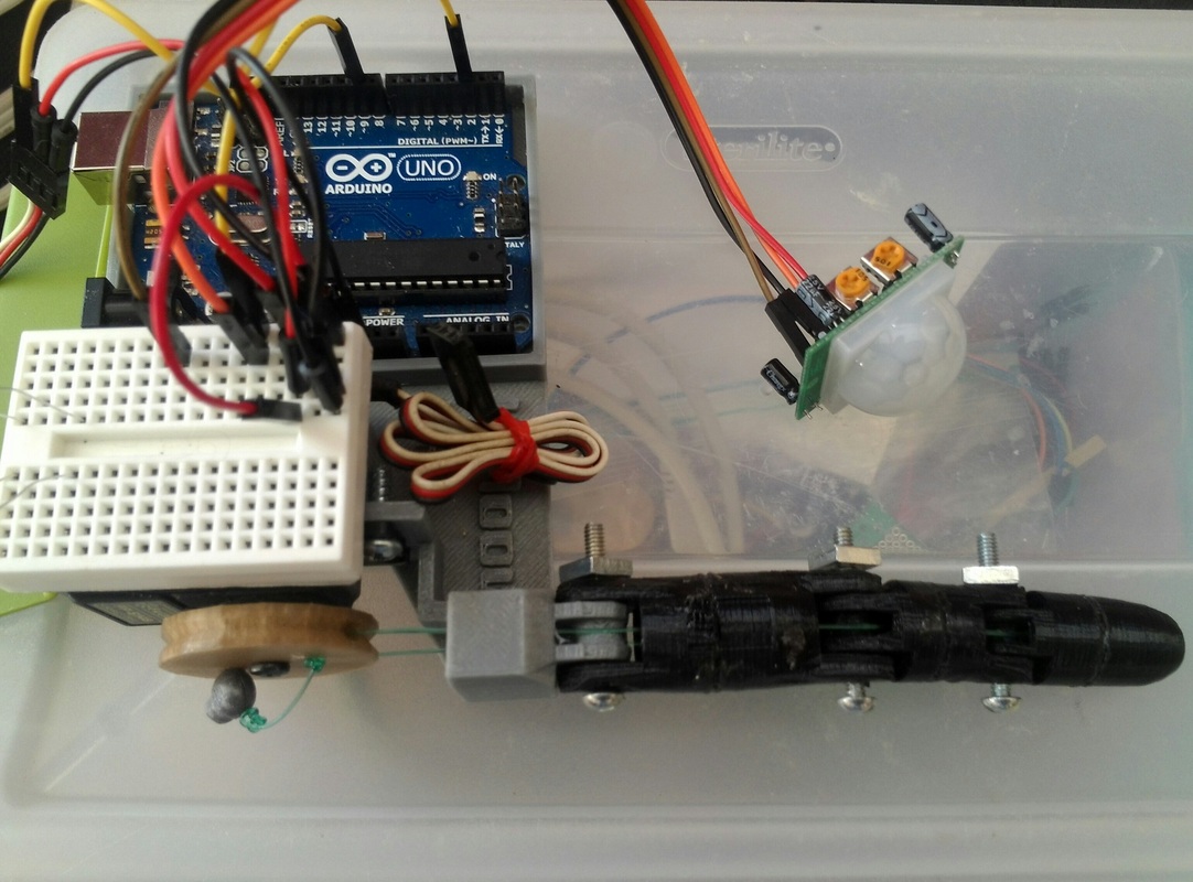
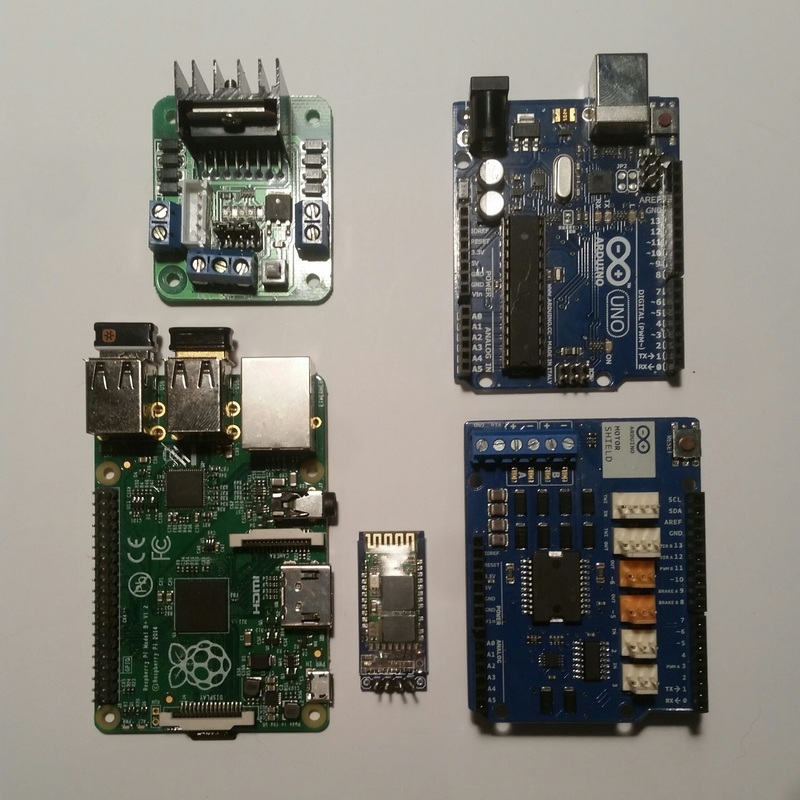
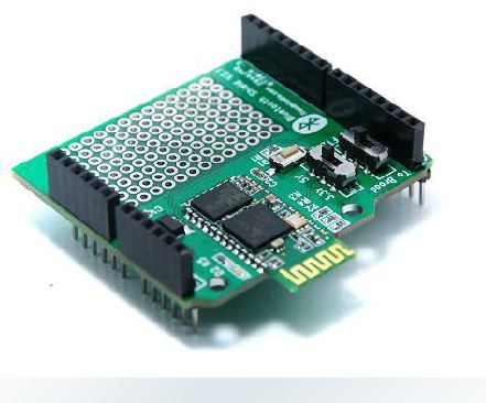
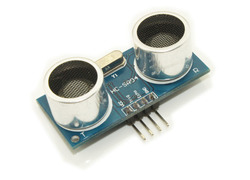
Once you have a rolling chasis with a drive train it's time to get creative and decide what components to load up your chasis with.  Ive used Arduino and RaspberryPi boards as my controller paired with motion sensors, ultra sonic distance sensors, light sensors etc.  Ive also had success controlling the device wirelessly using both bluetooth and wifi modules.
Picture
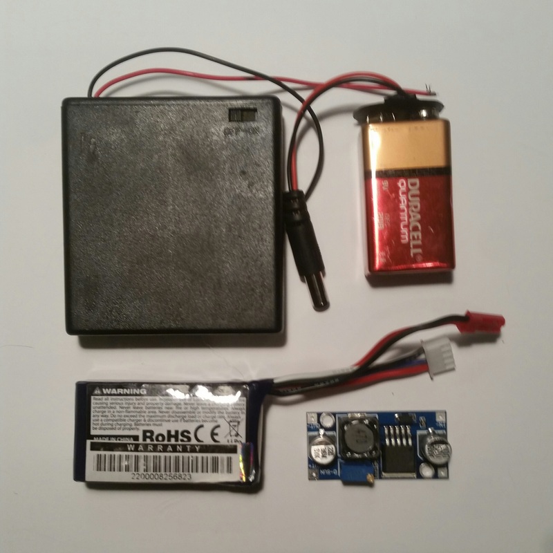
Once you've decided what components willbe on your vehicle, its time to select a power source.  wether you keepit simple with AA and 9 volt batteries or youtry to save some space and weight by using a rechargable lipo battery with a voltage regulator, you will need to pay attention to the different voltage and amperage limitations of each of your chosen components.  For example, your motors can likely handle 6 volts or more, but a raspi should only be supplied with 5 vdc.
Picture
Picture

InMoov Hand With MyRobotLab Voice Control

7/24/2015

 
Picture
With previous success animating my InMoov hand with arduino its time to get started with My Robot Lab.  There are useful tutorials available on the MyRobotLab website at http://myrobotlab.org/tutorials
At first I was a little nervous about using the command line interface (cli) but after saving the mrl.jar file to my c drive and typing the commands into the cli exactly as shown on the "starting a new mrl" tutorial I was pleasantly surprised to see a graphical user interface (gui) for MyRobotLab (mrl)
Picture
Java? Python? Whatt are these guys talking about?
MyRobotLab is written in Java, so it should run on Windows or Linux.  Inside of MyRobotLab there are many useful services, including the Python Service which allows code written in Python to interact with the other services.  The Arduino microcontroller is supported by the Arduino service in MyRobotLab and can be used to connect inputs and outputs to MyRobotLab.
Picture
Below is a video using MyRobotLab conneted to my InMoov right arm, through an Arduino.  The Arduino has the mrlcomm.ino sketch installed and MyRobotLab is running a modified version of the Inmoov.minimal.py example code with custom gestures created using the InMoov gesture creator service.  See more on my instructable Making InMoov Move.

Success!  Or as they say at My Robot Lab "worky"!

LED SHADES

3/22/2015

 
After my successful POV Globe project, I have learned how to use a microcontroller with shift registers to cycle LEDs on and off quickly to create the illusion of a full display using persistence of vision.  Inspired by this instructable  http://www.instructables.com/id/EL-EE-DEE-Glasses-First-Prototype/
I decided to try making a wearable LED matrix.

In this LED matrix I'm using an Arduino Uno, two serial in parallel out shift registers, and a decade counter.  The shift registers light up each column in sync with the decade counter that provides the ground to the cathodes one row at a time.  Due to the speed of the circuit all the rows will appear to be lit up simultaneously.
Picture
For troubleshooting purposes, I wired everything up on my Radio Shack electronics lab.  Obviously this won't work as a wearable circuit, but its very convenient for prototyping.
In the photo below, you can see the wiring and soldering done on the backside of the shades.  Each row is soldered directly to the breadboard and soldered to the cathode of each LED in that row.  The columns are raised an 1/8" above the rows to avoid short circuits and soldered to the anodes of each LED in that column.
Picture
The Rave Shades Animator available on the instructable link above allows you to easily create custom animations.  By copy and pasting the 0 or 1 value to each cell, the binary to decimal conversion is done for you and formatted so the code for the frame drawn can be pasted directly into the Arduino program.
Picture
Picture
Here you can see a successful test of a 50th anniversary animation.  Now that everything is working, its time to shrink the circuit to make it wearable.

With the circuit working reliably, it is time to start on the cosmetic aspects of the LED shades.  I used a piece of 1/4" foam I had laying around to cover up the wire matrix, leaving only a small portion exposed for visibility, where I had previously drilled out the holes on the breadboard.  Next, I selected a pair of safety glasses to donate their hinged ear mounts to the cause.  The pair I selected had a good size cross section at the hinge that would provide a good base to hot glue the hinges to the bread board.
Now to squeeze a voltage regulator, Atmega 328 with crystal oscillator and capacitors, 2 serial in parallel out 8 bit shift registers, a 4017 decade counter, 8 npn transistors, various resistors, a 9V battery and a power switch all onto a reasonable size breadboard that can be hidden on the back of the wearer's head.
Picture
Now that the shades fit on my head, I'm getting close.  Just need to add some foam to the back of the circuit board, so there aren't 100 pins poking the back of my head, but I think I'll leave the circuit and wiring exposed for conversation.  Some slight tweaking of the shape and a little carefully applied black spray paint to make them look more like sun glasses and finally, a few custom animations to finish off this project.

InMoov

2/21/2015

0 Comments

 
Picture
Picture
I came across the InMoov project while I was browsing Thingaverse for something to 3D print and knew immediately I would have to accept the challenge of building the hand.  If you have never heard of InMoov you can check it out Here on the InMoov Home Page. To get started, I decided to try the finger starter.  I figured if I could get the index finger to work then the hand should be doable.  I had the parts for the index finger and the finger sarter base printed and I set up an Arduino Uno with a servo.  I was able to thread fishing line through the finger and attach to the servo.  With a simple sketch uploaded to the Arduino, I had the index finger working with three types of control.

Picture
With the index finger a succes, it was time to move forward with the hand.  Since I have no 3D printer, I had to use a combination of 3Dhubs.com and the local library MakerSpace to get the parts printed.  I've found 3Dhubs to be a great resource for affordable printing services, with hubs in my local area and more than 10,000 hubs globally to choose from.  However, I had the parts for the right hand printed for 5 cents a gram at the MakerSpace in my local library.  Keeping the parts organized is key here.

Picture
After hours of careful sanding and drilling, I had all the parts fitting together nicely and moving freely.  A little epoxy and 100lb fishing line and the hand was taking shape.  I don't have the forearm and servo bed printed yet, but can't wait to start animating the hand.
Picture
0 Comments

Android Controlled 4 Channel Bluetooth Relay

2/16/2014

0 Comments

 
Be the Master of the House with this home automation device.  Use your Android device to remote control four separate 115V appliances.  For this project I am using the bareduino plus kit from virtuabotix, a 4-channel relay board from Sainsmart, an HC-06 bluetooth module and an old power strip.  I am also using an android app and arduino sketch called Ardudroid by TechBitar that can be downloaded from the Google Play store.
After disassembling an old power strip for parts I modified my project box to fit the outlets, power switch, reset button and cord.  With some careful forming of the neutral wires I was able to connect and fit the relay board in place.  Build up the Bareduino so I can have the functionality of an Arduino without giving up my precious.  You can get more info about the build on my Instructable
0 Comments
<<Previous

    Author

    As a midnight maker I am inspired by the open source community to contribute and share some of the projects I have attempted.

    Categories

    All
    3D Printing
    Arduino
    Crafts
    Drones
    Electronics
    InMoov
    LED
    Natural User Interface
    POV
    VR

    Archives

    August 2017
    February 2017
    November 2016
    October 2016
    September 2016
    July 2016
    March 2016
    February 2016
    November 2015
    September 2015
    July 2015
    April 2015
    March 2015
    February 2015
    January 2015
    February 2014

"We cannot solve a problem by using the same kind of thinking we used when we created them."  [Albert Einstein]