After my successful POV Globe project, I have learned how to use a microcontroller with shift registers to cycle LEDs on and off quickly to create the illusion of a full display using persistence of vision. Inspired by this instructable http://www.instructables.com/id/EL-EE-DEE-Glasses-First-Prototype/
I decided to try making a wearable LED matrix.
In this LED matrix I'm using an Arduino Uno, two serial in parallel out shift registers, and a decade counter. The shift registers light up each column in sync with the decade counter that provides the ground to the cathodes one row at a time. Due to the speed of the circuit all the rows will appear to be lit up simultaneously.
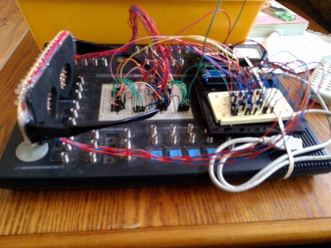
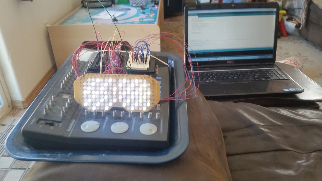 | For troubleshooting purposes, I wired everything up on my Radio Shack electronics lab. Obviously this won't work as a wearable circuit, but its very convenient for prototyping. |
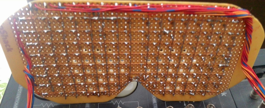
In the photo below, you can see the wiring and soldering done on the backside of the shades. Each row is soldered directly to the breadboard and soldered to the cathode of each LED in that row. The columns are raised an 1/8" above the rows to avoid short circuits and soldered to the anodes of each LED in that column.
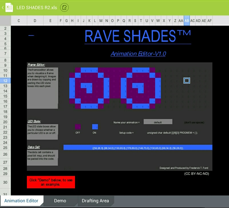
The Rave Shades Animator available on the instructable link above allows you to easily create custom animations. By copy and pasting the 0 or 1 value to each cell, the binary to decimal conversion is done for you and formatted so the code for the frame drawn can be pasted directly into the Arduino program.
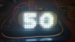
Here you can see a successful test of a 50th anniversary animation. Now that everything is working, its time to shrink the circuit to make it wearable.
With the circuit working reliably, it is time to start on the cosmetic aspects of the LED shades. I used a piece of 1/4" foam I had laying around to cover up the wire matrix, leaving only a small portion exposed for visibility, where I had previously drilled out the holes on the breadboard. Next, I selected a pair of safety glasses to donate their hinged ear mounts to the cause. The pair I selected had a good size cross section at the hinge that would provide a good base to hot glue the hinges to the bread board.
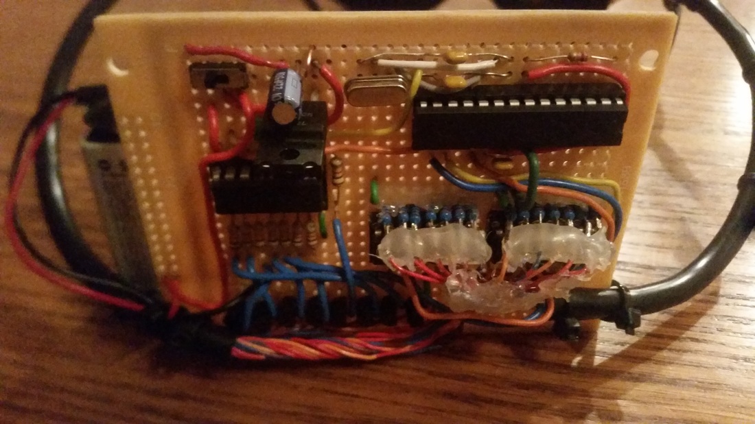
Now to squeeze a voltage regulator, Atmega 328 with crystal oscillator and capacitors, 2 serial in parallel out 8 bit shift registers, a 4017 decade counter, 8 npn transistors, various resistors, a 9V battery and a power switch all onto a reasonable size breadboard that can be hidden on the back of the wearer's head.
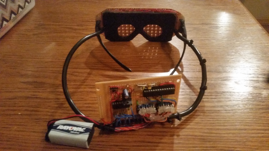
Now that the shades fit on my head, I'm getting close. Just need to add some foam to the back of the circuit board, so there aren't 100 pins poking the back of my head, but I think I'll leave the circuit and wiring exposed for conversation. Some slight tweaking of the shape and a little carefully applied black spray paint to make them look more like sun glasses and finally, a few custom animations to finish off this project.